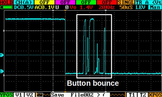
Reading the input from a button is one of the first challenges that a budding embedded software engineer comes across when bringing up his or her first interactive microcontroller project. What seems like a trivial task is in fact challenging because things are not perfect in the real world. A simple press of a tactile push button does not yield a single, perfect transition from one voltage level to another (high to low, or low to high). The button press is an external step input from the user. It creates an oscillation in the button, mechanically and electrically. The button contacts open and close, or “bounce”, in quick succession before a steady value is reached. Bounce occurs every time the button is pressed and also when released. A series of fast transitions between voltage levels is created, which must be dealt with in some way. How should the button input level be treated during this time? Is the button open or closed? How should the software respond to this abruptly changing input signal? Does it make sense to respond to an input level that is changing so rapidly?
Before we go any further, let’s have a look at two different ways to read an input value from a microcontroller.
- Read the value of the pin at a fixed time interval (“poll” the pin) in the main flow of the program. Let’s call this the polling method.
- Configure the pin to generate an interrupt when the pin level changes (a transition is detected) as a result of a button press. Let’s call this the transition detection method.
Polling method
This method simply samples the value of the input pin at a fixed time interval. This duty is performed by the microcontroller CPU, which means that it costs processing power and time. If you have 100 buttons or more, say a keyboard, then your CPU will be very busy with reading the level of each key switch. At first, it may seem that this method may be the answer to our issue; we can choose a sampling time interval which is longer than the typical period where button bounce occurs. It turns out that this period varies substantially for different button types (see Jack Ganssle’s great article on the topic). A polling interval exceeding the bounce period can also make the button feel unresponsive or slow by the user. A typical button bounce period for a tactile switch can be tens of milliseconds. A typical polling period which maintains user responsiveness is 5-10ms. How do we deal with this situation?
Transition detection method
This method requires your microcontroller to have a special feature, where a change in pin level (low to high or high to low) is first signalled to the interrupt controller and not the CPU. It allows the CPU to continue performing other tasks and not have the added burden of checking the pin level at constant time intervals. It is sometimes called interrupt-on-change. Lots of contemporary microcontrollers have this functionality. They include 8-bit Microchip PIC16s all the way through to the latest 32-bit STM32H7s. But what happens when a button is pressed and a rapid succession of level changes occurs? Does the CPU now need to deal with a whole lot of interrupt requests? Is this really any better than the polling method?
You now see that there are issues that we need to address for both methods of detecting button presses. In this post, we’ll address the issues with the polling method.
We know that if we want to poll the level of the button pin, we need to do it reasonably fast to maintain responsiveness. This time interval is often shorter than the typical button bounce duration. We also do not want our software to react to the abrupt pin level changes during the bounce period. There is a neat way to address this problem. It involves a little bit of logic and a software concept called “state”. We can characterise the action of pressing and releasing a button into four discrete phases, or “states”. These are:
- Button open- the button is not actuated and the electrical contacts are open
- Button closing- the user is pressing the button and button bounce is occurring
- Button closed- the button is pressed and held by the user and button bounce is no longer occurring
- Button opening- the user is releasing the button and button bounce is occurring
Please note that these states assume that we are dealing with a button with normally open contacts (open circuit in the unactuated state). Also, if the pin level is low when the button is actuated, we call it an “active low” button. Conversely, if the pin level is high when the button is actuated, the button is an “active high” button.
The state of the button can change when a transition occurs. A transition is only executed when a predetermined condition (or set of conditions) is satisfied. For example, the button state can only transition from “open” to “closing” when a corresponding pin level change is detected (high to low for active low, low to high for active high).
In order for the state to transition from closing to closed, two conditions must be valid:
- The debounce period has passed
- The pin level corresponds to a closed button (low for active low, high for active high)
When in the closed state, the transition to “opening” can only occur when a corresponding pin level change is detected (low to high for active low, high to low for active high).
The transition from opening to open can only occur when:
- The debounce period has passed
- The pin level corresponds to an open button (high for active low, low for active high)
All this information is not very easy to understand in written form. It is much clearer when shown as a diagram.
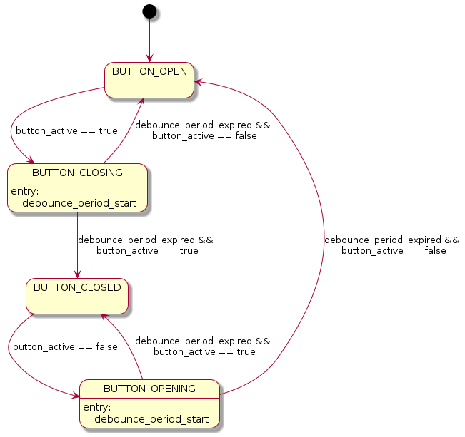
The states are represented by boxes and the transitions are the arrows. The text next to the arrows describes the conditions of the transition. It is much clearer to see all the possible transitions to and from the various states and the conditions associated with the transitions. Our simple example of processing a button press makes for a rather trivial state diagram, but you should see how powerful this concept is. It can be applied to very complicated systems with many different states, each with many transitions to many other states. In fact, it is also possible to have composite states, where one higher-level state can have two or more nested sub-states. Please refer to Miro Samek’s excellent book for more information on the topic of hierarchical state machines.
I’ll return to the transition detection method in a later post, but for next time, we’ll implement our button input processing strategy using the Nordic nRF51 development board and the nRF5 software development kit (SDK).